The basics of the PROFINET topology

Chapters
Below you will find the parts: PROFINET topology, Checking the line depth, Planning of the IO cycle from the PI Design guideline of PROFINET. We have included these on our website to quickly inform you about these important items. Would you like to download the full guideline? Then of course you can. Find it here.
PROFINET topology
The following pages of this section will introduce the different basic PROFINET topologies.
Flexibility in network design and layout is a key feature of PROFINET. Since all standard Ethernet topologies are used, PROFINET supports an almost unlimited number combination options.
The network topology mainly results from criteria such as:
- the location of the components,
- the distances to be covered,
- the EMC requirements,
- electrical isolation requirements,
- conformance class requirements,
- requirements for increased availability and
- consideration of network loads.


The different basic topologies of PROFINET are presented on the following pages of this section.
Star topology
The star topology is suitable for areas with limited geographical extension. A star-topology is automatically created if several communication nodes are connected to a common switch.

Figure 3-1: Star topology
If a single PROFINET node fails or is removed, the other PROFINET nodes will continue to operate. However, if the central switch fails, the communication to all the connected nodes will be interrupted.
Tree topology
A tree topology is created by combining several star-shaped networks to one network. Plant parts forming a functional unit are combined to star points. These are inter-networked via neighboring switches.
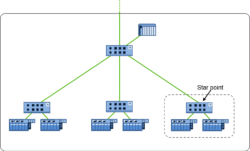

Figure 3-2: Tree topology
One switch operates as a signal distributor in the star point. Since the switch routes messages based on an address, only those messages will get to a neighboring distributor which are really required at this distributor.
Line topology
The line is a well-known topology used in automation. It is used for applications in extensive automation plants such as conveyor belts, but also for small machine applications. PROFINET devices equipped with an integrated switch facilitate the realization of line topologies.
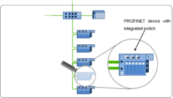

Figure 3-3: Line topology
The line is a well-known topology used in automation. It is used for applications in extensive automation plants such as conveyor belts, but also for small machine applications. PROFINET devices equipped with an integrated switch facilitate the realization of line topologies.
Checking the line depth
Each switch that is placed between a device and its controller introduces a delay in the data transfer. The number if switches between a controller and a device is called the line depth. The designer must take account of the line depth in the proposed topology. A line topology will exhibit a significant line depth because of the integrated switches in the devices. A large line depth will introduce delay which must be taken into account when planning the topology.

Figure 5-12 shows an example with a line depth of 9.
Usually, critical communication relations occur between devices and controllers. If more than one controller is involved, the devices assigned to each controller must be considered.
The larger the line depth, the larger the delay of data transmission. As a result, the data will have a certain age when it arrives at the destination. Excessive line depth should be avoided for time-critical applications.

The maximum line depths listed in Table 5-1 are valid for “Store and Forward” switches.
When using “Store-and-Forward” switches, the maximum line depths specified in Table 5-1 apply.
Table 5-1: Maximum line depth with “Store-and-Forward” switches
| Maximum line depth with update time | |||
| 1 ms | 2 ms | 4 ms | 8 ms |
| 7 | 14 | 28 | 58 |
In a worst-case scenario, the processing time for these line depths in a line topology is as large as the update time.
The maximum line depths listed in Table 5-2 are valid for “Cut Through” switches.
Table 5-2: Maximum line depth with “Cut Through” switches
| Maximum line depth with update time | |||
| 1 ms | 2 ms | 4 ms | 8 ms |
| 64 | 100 | 100 | 100 |
It is recommended to plan a maximum line depth of 45, for the benefit of higher availability and easier diagnosis.
This also allows future extensions using media redundancy (MRP).
If it should not be possible to observe the values specified in Table 5-1 resp. Table 5-2. You should re-design the structure of your network. It is, for example, possible to segment line topologies to achieve several short lines, as shown in Figure 5-13.

Figure 5-13 Example of reduced line depth.
The re-structuring options depend on the structure of your individual plant. Possible additional expenditure for supplementary switches or cabling is compensated by a higher plant availability and shorter plant response time.
Planning of the IO cycle
The following section deals with the definition of the device configuration. In this context, the PROFINET update times and monitoring functions are discussed.
Planning of update times
Controllers operate cyclically with a specified update time. The update time of all other PROFINET devices must be defined as a function of the controller cycle time. For multi-controller applications the devices assigned to the corresponding controller must be considered.
With fast update times the data will be updated at shorter intervals. As a result, they will be available for processing more quickly. However, the data volume transmitted in a time period and, thus, the network load are increased.
Figure 5-9 illustrates how the network load increases as a function of the update time and the number of network nodes, using the typical PROFINET packet size 108 bytes (60 bytes payload data) as an example.

Figure 5-9: Cyclic PROFINET network load as a function of update time and number of network nodes (typ. PROFINET packets)
When the network load is increased by cyclic real-time communication, the bandwidth available to other communications decreases. The network load topic is detailed in chapter 5.3.2 of the Designguideline.
The faster the update time, the larger the bandwidth occupied by cyclic real-time communication.
The slower the update time, the slower the response time.
It is therefore recommended to choose the update time per PROFINET device as fast as required and as slow as possible.
• Bear in mind that you have to adapt the update times accordingly when using wireless transmission technologies.
• Check the response time of the entire system resulting from this.
• Document these specifications.
So far some important items around the PROFINET topology. Would you like to download the full guideline? You can find it here.